


Contents
Kawasaki Teryx KRX 1000 - Install Instructions
Application Notes
Supported Models : 2020-2021 Kawasaki Teryx KRX 1000
Note: The vehicle shown in this document is a modified 2021 Kawasaki Teryx KRX 1000. Your vehicle could have parts that may or may not be present in the pictures. The images are meant to be a reference only. If you have any questions regarding your installation please contact us at offroad@yawpower.com
Item List
| Item No. | Description | Qty. | Fuel Rail + Regulator Kit (Return Style Kit) | Fuel Rail + Pulsation Damper Kit (Returnless Style Kit) | Fuel Rail Upgrade Kit |
|---|---|---|---|---|---|
| 1 | KRX Fuel Rail | 1 | |||
| 2 | 3 Bar Regulator Pressure / Pulsation Damper ASY | 1 | |||
| 3 | KRX Return Backing Plate | 1 | |||
| 4 | KRX Pilot Hole Bushing | 1 | |||
| 5 | KRX OEM Injector Adapter | 2 | |||
| 6 | Stock Fuel Pressure Regulator Plug | 1 | |||
| 7 | 06 ORB Male to 5/16" EFI Male (Incl. O Ring) | 1 | |||
| 8 | 06 ORB Plug | 1 | |||
| 9 | 06 ORB to 04AN Male | 1 | |||
| 10 | 06 ORB to 06 ORB Coupler | 1 | |||
| 11 | 04AN E85 Rated Hose (65"), 45° / 45° Crimp Fittings | 1 | |||
| 12 | 04AN 90° Bulkhead | 1 | |||
| 13 | 04AN Bulkhead Nut | 1 | |||
| 14 | 04AN Stat-O-Seal | 1 | |||
| 15 | 4mm Wye Hose Barb | 1 | |||
| 16 | 4mm Black Silicone Hose (5") | 1 | |||
| 17 | 11" Cable Tie | 5 | |||
| 18 | 3" Miniature Cable Ties | 4 |
Fuel Rail + Regulator Kit (Return Style Kit)
1. Remove Fuel Pump Module
- Remove the passenger seat by unfastening (4) bolts securing the seat rail.
- Remove the plastic cover shown in figure 1.
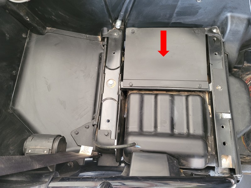
Figure 1: Pump access panel reference.
- Disconnect the power connector and crank the engine to bleed fuel pressure. Disconnect battery once the pressure has bled.
- Disconnect fuel line from the pump module. There will be some fuel left in the fuel line.
- Remove the fuel pump locking ring by removing (6) bolts and lifting the fuel pump module out of the tank (drain fuel back into the tank).
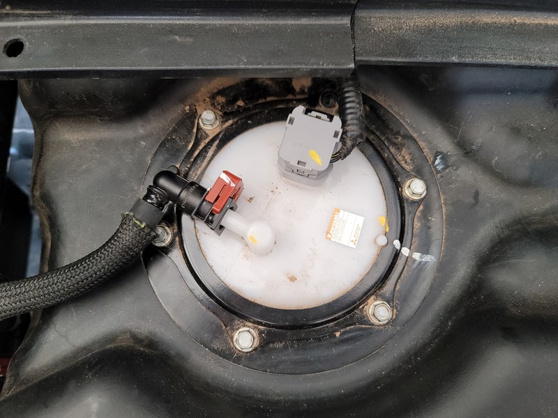
Figure 2: Pump connections reference.
2. Modify Fuel Pump Module for Return Line and Regulator Plug Installation
- Uninstall the pump top hat by disconnecting (2) electrical connectors and lifting on (4) clips shown in figure 3.
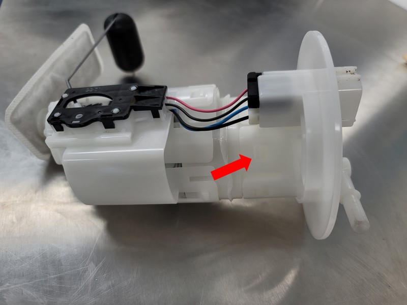
Figure 3: Top hat clips reference.
- Using side cutters, cut the center webbing shown in figure 4.
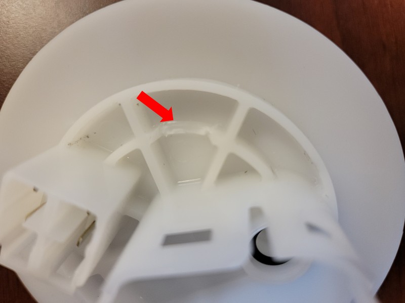
Figure 4: Top hat web reference.
- Insert the backing plate into the webbing of the top hat. Next, insert the pilot hole bushing as shown in figure 5.
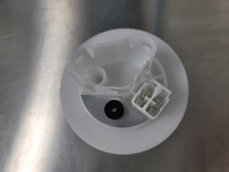
Figure 5: Backing plate and bushing reference.
- Drill a 1/8” hole using the center hole of the bushing. Remove the bushing and backing plate.
- From the top side of the top hat, drill a 7/16” hole. A Unibit is recommended but it is also possible to start with a smaller drill bit and step up to a 7/16” bit.
- Install the -04 90° bulkhead fitting using the stat-o-seal on the top of the top hat. Use figure 6 as a reference for the orientation of the bulkhead fitting.
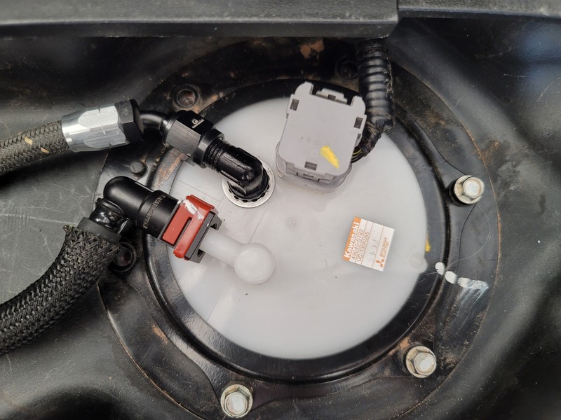
Figure 6: Return line orientation reference.
- Remove the bottom half of the fuel pump module by lifting on the clips shown in figure 7. Make sure not to lose the O-ring that sits on the pump outlet.
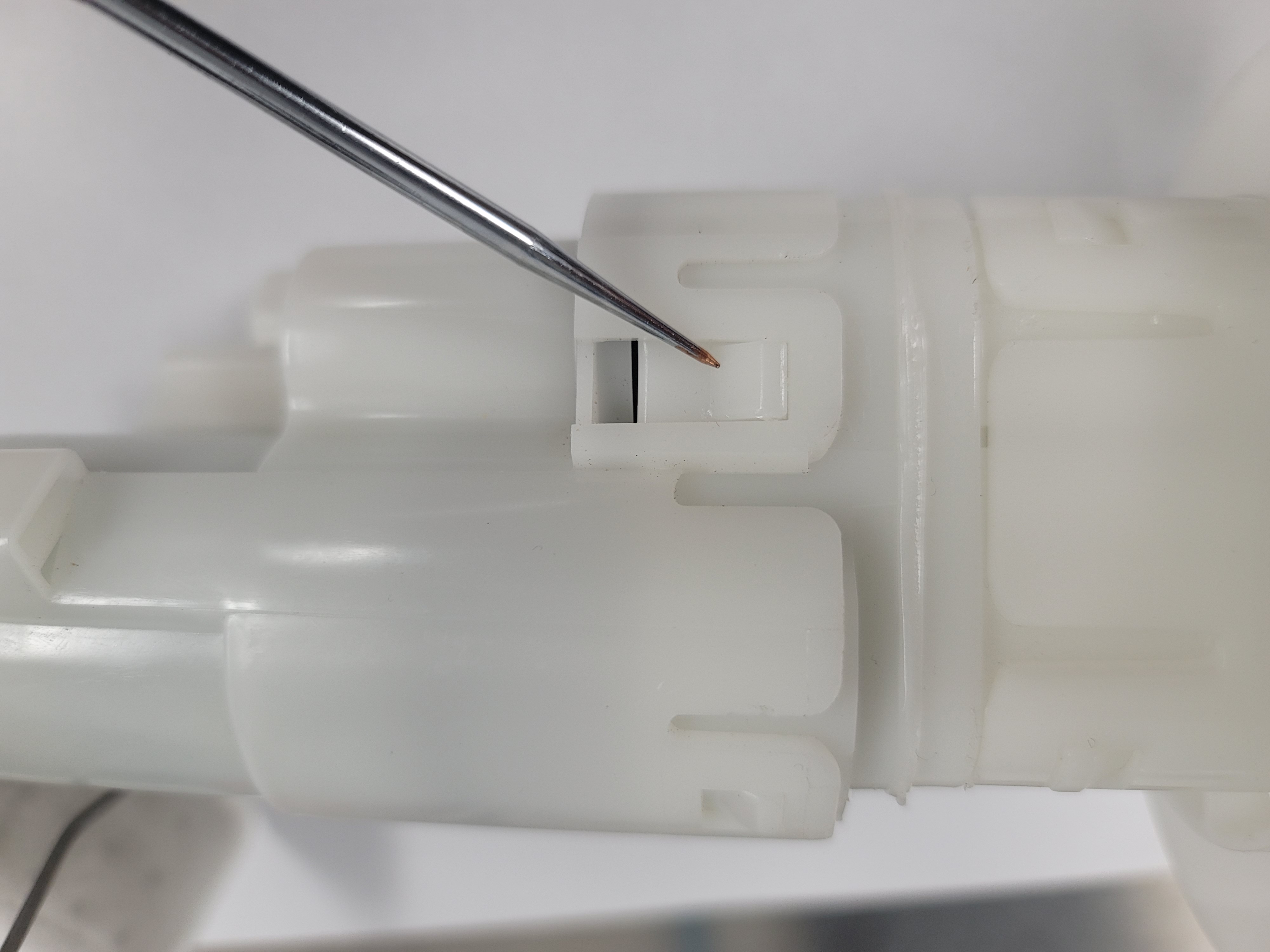
Figure 7: Clip reference.
- Remove the factory fuel pressure regulator.
- Insert the supplied regulator plug into the fuel pump module.
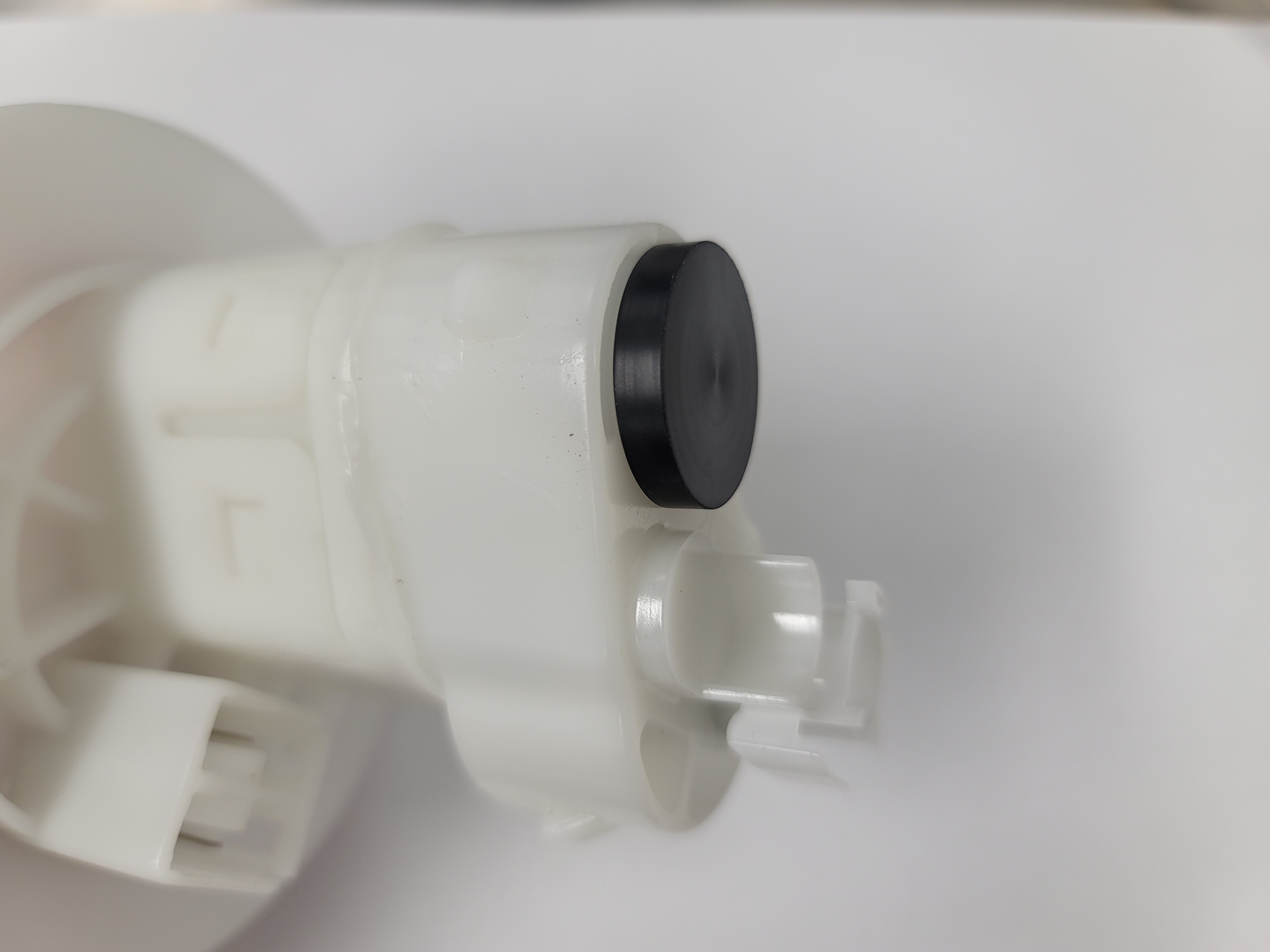
Figure 8: Installed regulator plug.
- Reassemble the fuel pump module.
- Reinstall the fuel pump module into the fuel tank. Use figure 2 as a reference for all connections.
3. Install Fuel Rail, Injectors and Regulator
- Remove the trunk panel to gain access to the top of the engine.
- Disconnect injector electrical connectors.
- Disconnect the fuel line from rail. There will be fuel left in the fuel line.
- Remove (2) Phillips head bolts to uninstall the fuel rail.
- Install the supplied fittings on the rail and regulator.
- Install the -06 ORB to 5/16” EFI fitting on the inlet of the rail (driver’s side).
- Install the -06 ORB swivel fitting (non adjustable side) on the outlet of the rail (passenger’s side).
- Install the -06 ORB to -04 AN fitting into the bottom of the regulator housing.
- Thread on the regulator housing to the swivel fitting until the threads bottom out, then back out one turn. Do not tighten the lock nut.
- Install ID injectors into the fuel rail (Apply grease on all O-rings).
- Install fuel rail and injectors onto the throttle body ensuring both injectors are firmly seated (Take care, not to over tighten bolts).
- Orientate the fuel pressure regulator as seen in figure 9.
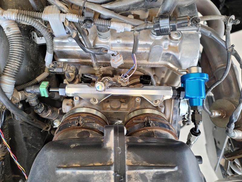
Figure 9: Pressure regulator orientation reference.
- Reconnect the factory fuel line.
- Reconnect injector connectors using the supplied electrical adapters.
- Connect the vacuum hoses for manifold pressure reference:
- Cut the factory vacuum line 2 inches away from the T shown in figure 10 and push on the supplied Wye fitting onto both ends of the cut line.
- Insert the supplied 4mm vacuum hose onto the last leg of the Wye fitting.
- Trim any excess length of the vacuum hose and push onto the pressure regulator barb.
- Secure a zip tie onto all hose ends.
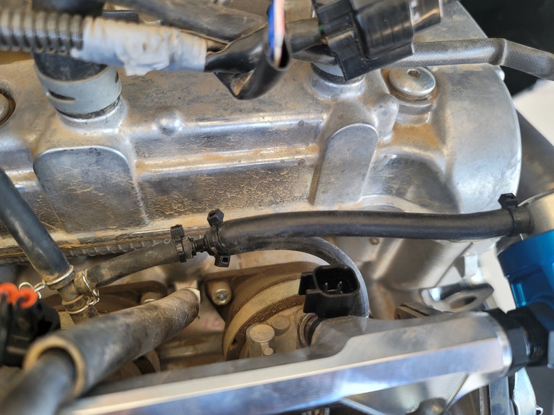
Figure 10: Vacuum line reference.
4. Install Return Line
- Pass the return line through the firewall alongside the feed line and tighten the fitting at the pump first. Pull all slack towards the rear of the car.
- Tighten the fitting to the fuel pressure regulator.
- Secure the return line to the feed line using zip ties. Use figure 11 as a reference.
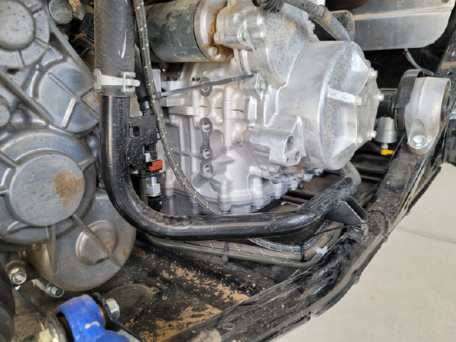
Figure 11: Return line routing reference.
- Reconnect battery and prime the fuel system to check for leaks. Do not start the vehicle.
5. Flash ECU
- Generate ECU data by using the online generator at the link below and follow the directions to change the calibration.
Dynojet PV3 Kawasaki Data Generator - Once the ECU flash is complete, start the vehicle ensuring that there are no leaks in the fuel system (Caution: It is best to have a fire extinguisher within reach).
6. Reinstall All Remaining Parts
- Once you have ensured there are no leaks, reinstall all body panels and seats in the reverse order of removal.
Fuel Rail + Pulsation Damper Kit (Returnless Style Kit)
1. Install Fuel Rail, Injectors and Pulsation Damper
- Remove the trunk panel to gain access to the top of the engine.
- Disconnect injector electrical connectors.
- Disconnect the fuel line from rail. There will be fuel left in the fuel line.
- Remove (2) Phillips head bolts to uninstall the fuel rail.
- Install the supplied fittings on the rail and pulsation damper.
- Install the -06 ORB to 5/16” EFI fitting on the inlet of the rail (driver’s side).
- Install the -06 ORB swivel fitting (non adjustable side) on the outlet of the rail (passenger’s side).
- Install the -06 ORB plug fitting into the bottom of the pulsation damper housing.
- Thread on the pulsation damper housing to the swivel fitting until the threads bottom out, then back out one turn. Do not tighten the lock nut.
- Install ID injectors into the fuel rail (Apply grease on all O-rings).
- Install fuel rail and injectors onto the throttle body ensuring both injectors are firmly seated (Take care, not to over tighten bolts).
- Orientate the pulsation damper as seen in figure 1. NOTE: You will not have a return line connected to the pulsation damper.
Figure 1: Pulsation damper housing orientation reference.
- Reconnect factory fuel line.
- Reconnect injector connectors using the supplied electrical adapters.
- Reconnect battery and prime the fuel system to check for leaks. Do not start the vehicle.
2. Flash ECU
- Generate ECU data by using the online generator at the link below and follow the directions to change the calibration.
Dynojet PV3 Kawasaki Data Generator - Once the ECU flash is complete, start the vehicle ensuring that there are no leaks in the fuel system (Caution: It is best to have a fire extinguisher within reach).
3. Reinstall All Remaining Parts
- Once you have ensured there are no leaks, reinstall all body panels and seats in the reverse order of removal.
Fuel Rail Upgrade Kit
1. Install Fuel Rail and Injectors
- Remove the trunk panel to gain access to the top of the engine.
- Disconnect injector electrical connectors.
- Disconnect the fuel line from rail. There will be fuel left in the fuel line.
- Remove the (2) Phillips head bolts to uninstall the fuel rail.
- Install the supplied fittings on the rail.
- Install the -06 ORB to 5/16” EFI fitting on the inlet of the rail (driver’s side).
- Install the -06 ORB plug on the outlet of the rail (passenger’s side).
- Install the OEM injectors into the fuel rail using the supplied injector adapters (Apply grease on all O-rings).
- Install fuel rail and injectors onto the throttle body ensuring both injectors are firmly seated (Take care, not to over tighten bolts). Use figure 1 as a reference.
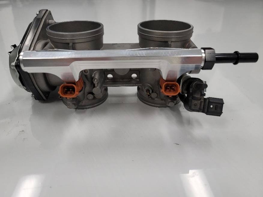
Figure 1: Rail reference.
- Reconnect the factory fuel line.
- Reconnect the injector connectors.
- Reconnect the battery and prime the fuel system to check for leaks. Do not start the vehicle.
2. Reinstall All Remaining Parts
- Once you have ensured there are no leaks, reinstall all body panels and seats in the reverse order of removal.